Vietnamese standards for cable tray ladders are regulated and issued to ensure technical quality in design and construction. If you need a cable tray ladder, you cannot ignore this standard.
We share the content of cable tray ladder standards in the next part of the article.
Cable tray design standards
Designing a cable ladder system that meets technical requirements helps reduce costs and shorten completion time. Current popular cable tray design standards are as follows:
Cable tray ladder materials
The material of the cable tray ladder is suitable for environmental conditions. In addition, it must meet technical safety standards. Some types of materials used to produce cable ladders are:
- Galvanised aluminium
- Stainless steel
- Surface powder coating
- Hot dip galvanized
Thickness of cable tray ladder
The thickness of cable ladders and cable trays depends on the material.
- Powder coated cable tray ladders have thicknesses: 1, 1.2, 1.5 and 2
- Hot-dip cable tray ladder has thickness: 1.5 and 2
Allowable load of cable tray ladder
The load of the cable tray ladder is the deflection between the two support points <1/300 span. Calculating the load allows determining the sturdiness and safety of the cable tray ladder.
Distance between cable ladder supports
The standard distance is 1.5m – 2m. For heavy cable ladders, trees are needed to support the heavy load.
The radius of curvature
Accessories and cable size determine the bend radius.
- Cable outer diameter <100, R 400mm
- 100<outer diameter<160, R600mm
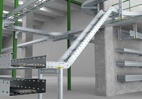
Standards for installing cable ladders
Installation of cable tray ladders complies with the provisions of Standard TCVN 9208:2012 of the Ministry of Science and Technology. The content is specified in Articles 6 and 7 of the Document.
Article 6: Install cables and electrical wires in trays and cable ladders
6.1. A system of cable trays and ladders must be used to protect electric cables within a factory with a large number of cables.
6.2. The cable tray and ladder system must be completely installed before cable placement.
6.3. Where necessary, tray and cable ladder systems should be installed with elbows, joints, cross stitches, narrowing stitches, tray covers and other accessories.
6.4. The cable tray or ladder route must not be wider than 1200 mm, there must be a support or hanging light after each distance from 1 m to 3 m, this distance must be approved by a competent authority before construction.
6.5. Support beams or hanging beams must be fixed to building structures or welded to steel bars embedded in the concrete structure of the ceiling.
6.6. Cable trays and ladders must be large enough so that all the cables inside are spread out in one layer. The gap between two adjacent cables must be enough to tie the cable to the horizontal latch of the ladder or the bottom of the cable tray with a plastic tie.
6.7. Materials used to make cable trays or ladders must be hot galvanized steel or have an outer coating of anti-rust and anti-corrosion materials.
6.8. The cables in cable trays and ladders must be arranged in order, divided into groups depending on function and fixed with plastic ties.
6.9. Cable trays and ladders must have appropriate strength and stiffness to support all cables contained in the cable tray or ladder.
6.10. Cable trays and ladders must not have sharp edges, rough surfaces or burrs so as not to damage the insulation or outer shell of the cable. Screws and bolts must not protrude from the inside of the tray or cable ladder.
6.11. In places where elbows, clamps, cross stitches, narrow stitches, etc. are used, the tray or cable ladder must be electrically continuous, but the tray or cable ladder itself must not be used as a ground wire.
6.12. Where cables from cable trays or ladders are inserted into conduits or other means of enclosure, sturdy supports must be provided to prevent strain on the cables.
6.13. In places where cable trays or ladders are at risk of dust accumulation or falling materials, or heat effects, consideration must be given to arranging additional protective means such as roofing, ventilation fans, etc.
6.14. When it is necessary to avoid hydraulic mechanical pipes or construction structures, detailed drawings of modified tray or ladder sections must be submitted to the design consulting agency for approval before construction.
6.15. Where rainwater seeps through openings arranged along tray lines or cable ladders, measures to prevent water intrusion must be considered.
6.16. Vertical cable ladder routes must be protected with anti-corrosion and mechanical damage metal covers within 2 m from the finished floor or ground level or above.
6.17. Sufficient space must be left or maintained around the cable tray or ladder to permit easy access for cable installation and maintenance.
6.18. Cable trays and ladders must be grounded and connected to the nearest ground wire. Long cable trays and ladders must be grounded repeatedly after a certain distance as prescribed by the design for each project.
6.19. The cable must be firmly fixed to the horizontal latch of the ladder or the perforated bottom of the tray with a plastic tie every distance from 3 m to 1.5 m for routes running horizontally or from 1.5 m to 0, 5 m for routes running in the other direction. The larger the cable, the shorter the tie distance.
6.20. The top cover of the cable tray or ladder and any additional protective means shall be easily removable.
6.21. Where cable trays or ladders run through the ceiling, wall or floor separating air-conditioned rooms from non-air-conditioned rooms, the openings must be sealed and insulation between rooms must be ensured. .
6.22. Cables going from inside the tray or cable ladder to the outside must not go over the side wall of the tray or cable ladder so as not to obstruct the cover of the tray or cable ladder.
6.23. When there are multiple levels of low-voltage cable trays or ladders running parallel under the ceiling in the same direction, each layer running above the other, the distance between two consecutive floors must not be less than 200 mm. The distance of the top floor from the nearest ceiling or beam should not be less than 300 mm.
6.24. When there are multiple floors of low-voltage cable trays or ladders running parallel along the technical corridor, one floor running above the other, the distance between two consecutive floors must not be less than 300 mm. The distance of the bottom floor to the top of the technological pipe layer running below must not be less than 500 mm.
6.25. Medium-voltage cable trays or ladders must be located away from low-voltage cable trays or ladders. This distance is usually not less than 500 mm and must be approved by the investor’s engineer in charge of supervising electrical construction.
6.26. Cable trays or ladders must not be connected to oil or gas pipelines in the same technical corridor.
6.27. Each cable tray or ladder must be in a freely elastic position on supports or hanging cables.
6.28. When the cable route running horizontally changes to vertical or vice versa, the cable tray or cable ladder turns through two 135° bending angles.
6.29. Medium voltage cable trays or ladders must have contrasting colors or signs to distinguish them.
6.30. Before installation, cable trays or ladders and accessories must be inspected to ensure there are no electrical or mechanical defects:
Visually check for strength, solidity, quality of welds and joints, coating, galvanizing, etc.
Check electrical continuity.
Article 7: Install cables and wires in the cable box
7.1. Cable boxes can be used to store wires and cables in places where the volume of wires and cables is not much and the cables have small diameters. Cable boxes must be made of metal or other materials with high mechanical strength.
7.2. The cable box system must be completely installed before placing wires or cables inside the tray.
7.3. The cable box must have a cover throughout its length. Covers must be easy to remove for ease of installation, maintenance, and replacement of wires and cables. Cable boxes and covers must not be joined at the passage through the wall or floor.
7.4. Cable boxes located in rainy areas must have a protection level no lower than IP23 and must have measures to prevent water and moisture from entering the cable box through the connections.
7.5. The shape and surface of the joints or direction changes of the cable box must be treated so that they do not damage the cables and wires placed inside.
7.6. The cable box must be installed so that it is easily accessible at any location along its length to inspect and repair the cables inside.
7.7. Cable boxes should not be placed in humid or flammable environments and places susceptible to mechanical damage without additional protection.
7.8. The wires and cables inside the cable box must be arranged in order and neatly to allow air to circulate and heat to dissipate easily.
7.9. The cable box must be hung or supported every 1.5 m and must be in a freely flexible position on the supports or hangers.
7.10. Hanging lights or brackets must be fixed to building structures or welded to steel bars embedded in the concrete structure of the ceiling.
7.11. The metal cable box must be grounded and connected to the nearest ground wire (but the metal cable box itself must not be used as a ground wire for another piece of equipment).


Bình Luận